The “slab model”#
Possibly the most common approach to simulating model reflectometry data for comparison with, and refinement against, experimental data is the slab model. This is called the slab model as we describe the system as a series of slabs, with particular thickness and scattering length density. In this section, we will describe a typical slab model construction before going on to discuss some nuances of the model and how the reflectometry is calculated in later sections.
An example of such a slab model is shown in Fig. 3 below. This slab model consists of two layers, with thicknesses of \(d_1\) and \(d_2\) and scattering length densities of \(\beta_1\) and \(\beta_2\). The scattering length density is a measure of how much the given material will scatter the incident neutron. As we will see in A case for model reparameterisation, these parameters can be defined in terms of our chemical and physical understanding of the system.
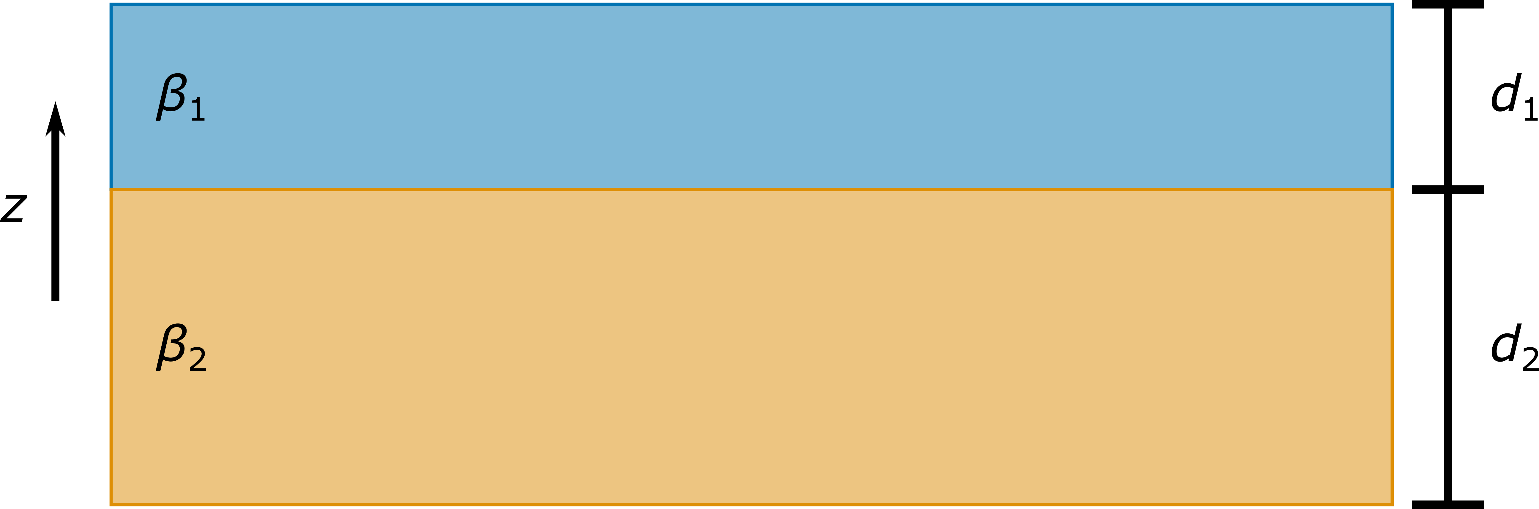
Fig. 3 An example of a simple slab model, showing the scattering length densities (\(\beta_1\) and \(\beta_2\)) the thicknesses (\(d_1\) and \(d_2\)) and the \(z\)-dimension.#
In Fourier transforms for reflectometry analysis, it was introduced that the first derivative of the scattering length density profile, i.e. the difference in scattering length density as a function of \(z\), was fundamental to the modelling of reflectivity. The importance of this is not lost in the slab models, where the model reflectometry data depends on the ratio between the scattering length densities in two layers. The reflectometry calculation from a slab model involves considering the reflection and refraction of the neutron wave at each interface. How much the wave is refracted at each interface depends on the ratio of the scattering length densities.
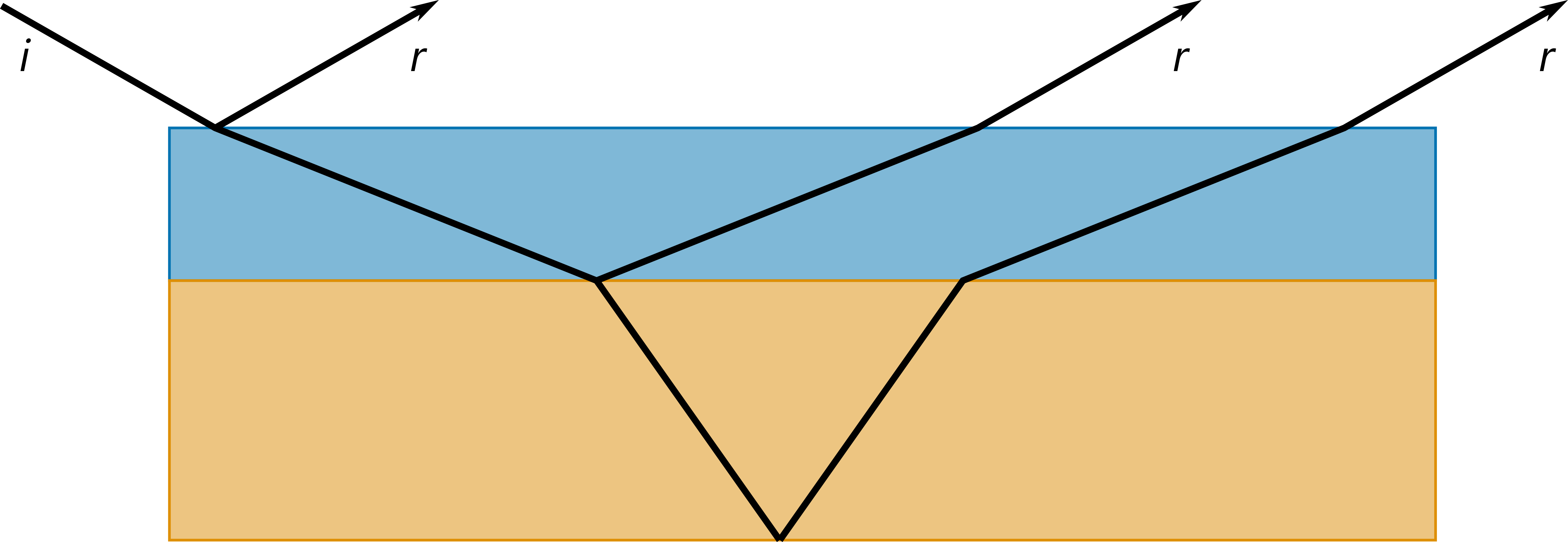
Fig. 4 The same slab model as shown in Fig. 3, showing the paths taken by the incident (i) wave that can result in the reflected (r) waves.#
Fig. 4 shows how the neutron wave propagates through the slab model in reflection geometry. Hopefully, it is clear how this would lead to constructive and destructive interference could be observed in this system by some detector that measures the reflected waves. It is this interference pattern that we measure when we measure the reflectometry profile, however, obviously real experimental systems are less ordered.